12kV 630A Special-Shaped Busbar
RIKI’s 12kV 630A special-shaped busbar is a multi-way insulated connection accessory available in two-, three- and four-connection configurations. The catalog describes its use in cable branch boxes associated with SF6 load switches or vacuum circuit breakers, including arrangements involving T-joints and cross-joints. Buyers should select the required connection layout and verify the mating interfaces, installation dimensions and complete assembly configuration before ordering.
Three Connection Points Do Not Automatically Mean Three Phases
The three-way version of a 12kV special-shaped busbar has three visible connection positions arranged along one molded body. That does not, by itself, identify the component as a three-phase busbar assembly.
The distinction is important when reviewing a cable branch box or switchgear drawing. A three-way connection arrangement may describe the number of mating positions in a particular electrical connection system, while the number of phases and the electrical relationship between the positions must be established from the approved circuit and product drawings.
RIKI offers this accessory in two-, three- and four-way configurations under the HY YMP-12/630 series. The published models identify the connection count, 12kV voltage class and 630A current rating. The catalog does not provide a complete internal connection diagram for each version.
The Number of Ways Is a Layout Decision
The three catalog codes are:
- HY YMP2-12/630: two connection positions.
- HY YMP3-12/630: three connection positions.
- HY YMP4-12/630: four connection positions.
Choosing among them should begin with the intended connection arrangement. The equipment drawing needs to show the required number of mating positions, their orientation and the compatible connecting accessories.
A two-way unit should not be selected simply because two cables enter a cabinet. Likewise, a four-way unit should not automatically be described as a four-feeder distribution assembly. The complete electrical function depends on how the component is incorporated into the approved equipment design.
Check the T-Joint and Cross-Joint Arrangement
The RIKI catalog describes the special-shaped busbar as an accessory used with cable branch boxes associated with SF6 load switches or vacuum circuit breakers. It also refers to cross-joints and T-joints as part of the connection arrangement.
For a replacement order, the important question is whether the new busbar will mate with the existing connector components. Matching the 12kV and 630A markings is not enough to establish the contact dimensions, mechanical fit or insulating interface.
The connection orientation should also be checked. A connector that has the required electrical rating may still be unsuitable if its mating position or available installation space does not match the intended arrangement.
European and American Connection Types Need Separate Identification
The manufacturer’s overview refers to European-type and American-type connection systems. However, the published HY YMP2, HY YMP3 and HY YMP4 ordering table does not separately identify which interface version is supplied under each code.
That distinction must therefore be resolved from the product drawing or a manufacturer-confirmed configuration. The term “630A” alone does not establish compatibility with every European or American separable connector system.
A purchasing request should identify the receiving equipment and the exact mating component whenever possible. If the existing connection model is unknown, obtain the relevant interface drawing before approving a substitute.
A Molded Busbar Is Not a Cable Branch Box
The special-shaped busbar is one component within a wider cable connection arrangement. It should not be confused with a complete metal cable branch enclosure or an ordinary copper busbar covered by insulating tubing.
The cabinet provides the equipment housing and supporting arrangements. Mating connectors, bushings and related components establish the relevant electrical connections. The special-shaped busbar must be selected for its intended position within that assembly.
RIKI describes the product as supporting fully insulated and sealed connection arrangements. That statement does not establish a standalone IP protection rating or confirm the performance of an assembled connection using unverified mating accessories.
What the Three-Way Photograph Can and Cannot Confirm
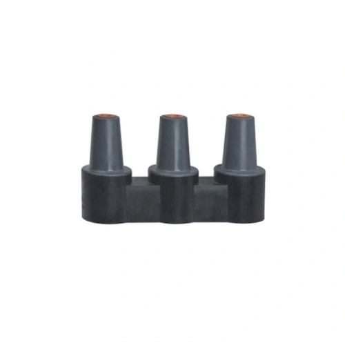
The supplied image shows three upright tapered connection sections joined by a single black insulating body. Metallic contact openings are visible at the upper ends.
The photograph confirms the general three-way construction, but does not establish the internal conductive arrangement, exact contact dimensions, insulation material grade or the interface standard.
For an OEM or replacement order, request the current dimensional drawing and the recommended mating-component list. Where project approval requires electrical tests or certification documents, confirm their applicability to the exact configuration being supplied.
Purchasing recommendation: submit the intended connection diagram, required two-, three- or four-way arrangement, switchgear model and mating connector identification. Confirm these details before ordering on the basis of the product picture alone.
12kV 630A Special-Shaped Busbar — Model and Connection Configuration
| Product Name | 12kV 630A Special-Shaped Busbar |
|---|---|
| Brand | RIKI |
| Catalog Model Family | HY YMP-12/630 |
| Product Category | Separable Cable Connectors |
| Product Type | Multi-Way Insulated Connection Busbar |
| Rated Voltage | 12kV |
| Rated Current | 630A |
| Available Connection Configurations | 2-Way, 3-Way and 4-Way |
| Insulation Arrangement | Insulated Molded Connection Assembly; Exact Material Specification Requires Confirmation |
| Catalog-Described Equipment | Cable Branch Boxes with SF6 Load Switches or Vacuum Circuit Breakers |
| Catalog-Described Connection Accessories | 630A Joints, Hybrid Joints, T-Joints and Cross-Joints; Exact Interfaces to Be Verified |
| Connection System | European-Type or American-Type Arrangements Mentioned in the Catalog; Specific Version Requires Confirmation |
| Product Color Shown | Black / Dark Gray |
| Dimensional Drawing | Required for Mating Interface Confirmation |
| Electrical Test Values | Not Published for This Specific Model in the Referenced Catalog Page |
| Product Certification | Model-Specific Documentation Requires Confirmation |
| Published Model Selection | |
| HY YMP2-12/630 | 2 Connection Positions — 12kV / 630A |
| HY YMP3-12/630 | 3 Connection Positions — 12kV / 630A |
| HY YMP4-12/630 | 4 Connection Positions — 12kV / 630A |
Frequently Asked Questions (FAQ)
Does a three-way special-shaped busbar connect three electrical phases?
Not necessarily. The three-way designation identifies three connection positions, not a confirmed three-phase electrical arrangement. The internal conductive configuration and relationship between connection points must be established from the applicable product drawing and equipment circuit diagram. Do not determine phase allocation from the number of visible interfaces.
Can the HY YMP series connect directly to any 630A T-joint?
The RIKI catalog mentions T-joints and cross-joints among the associated connection components, but it does not confirm universal interchangeability. The mating profile, contact dimensions, voltage class and insulation interface must match the selected assembly. Verify the T-joint model and approved connection drawing before ordering.
Are European-type and American-type versions interchangeable?
No automatic interchangeability should be assumed. The catalog discusses both connection-system types but does not assign a separate verified interface designation to each HY YMP ordering code. The required interface profile and mating accessory must be confirmed from the equipment and product drawings before a replacement or new installation is approved.
Does the 630A busbar include load-break switching functionality?
The 630A value is the rated current stated for the special-shaped busbar. The catalog describes its use in assemblies associated with load switches or circuit breakers, but it does not identify the busbar itself as a switching device. Switching, isolation and protection capabilities depend on the separate equipment design and should not be inferred from this accessory.
Can a four-way busbar replace a three-way model with one position left unused?
That substitution requires a specific engineering review. The additional position changes the physical arrangement and may require an approved insulating or sealing component if it is not connected. Confirm the circuit configuration, available space, mating interfaces and treatment of the unused position before substituting one model for another.
Connection Arrangements That Call for a Multi-Way Insulated Busbar
Multi-Point Connections Inside Cable Branch Equipment
A cable branch assembly may require several compatible connection positions within a defined enclosure. The special-shaped busbar provides a model family for two-, three- or four-way arrangements, subject to approval of the actual electrical connections.
Selection question: How many mating positions are shown in the connection drawing, and how are they electrically related?
Switchgear Connection Assemblies
The catalog describes applications associated with SF6 load switches or vacuum circuit breakers. The busbar must be matched to the equipment-side connection and the required T-joint or cross-joint arrangement.
Selection question: Which switchgear connection interface and compatible joint components are specified?
Replacement of an Existing Multi-Way Connection Component
Replacing a damaged or unsuitable molded busbar requires confirmation of its electrical function and physical interfaces. The number of visible connection positions alone cannot establish interchangeability.
Selection question: Is the original equipment model or component drawing available?
OEM Cable Connection Assembly Procurement
Equipment manufacturers may evaluate the two-, three- and four-way versions as parts of a coordinated 630A connection system. The proposed assembly should be reviewed with the associated connectors, installation geometry and required test documentation.
Selection question: Has the complete mating-component combination been verified?