A copper busbar may be specified as 80 mm wide, but that measurement alone does not determine the correct heat shrink sleeve. The bar thickness, joint geometry, bends and components that the tubing must pass over can all affect installation.
RIKI’s continuous busbar tubing is available in two voltage families: MPG10 for 10kV applications and MPG35 for 35kV applications. The catalog provides separate tables showing applicable busbar width, tubing inside diameter before and after shrinkage, and wall thickness at both stages.
These dimensions should be considered together. Choosing a sleeve only because its listed busbar width matches a drawing can produce problems when the actual copper profile or connection hardware is larger than the intended tubing opening.
The Same Nominal Size Has Different Wall Thicknesses
Consider the 50/25 designation. Both MPG10 and MPG35 have a nominal size option with that designation, but their insulation wall thicknesses differ.
- MPG10-50/25: published recovered wall thickness of 2.2 ± 0.1 mm.
- MPG35-50/25: published recovered wall thickness of 3.1 ± 0.1 mm.
The 35kV version therefore cannot be treated as the same tubing with a different label. This distinction should appear in the purchasing specification, particularly when two voltage classes are ordered for the same factory or project.
The catalog also lists fewer nominal sizes in the 35kV range. MPG10 has twelve options, while MPG35 has eleven. A 10kV ordering code should not be assumed to have an identically numbered 35kV replacement.
What Happens After Heating?
The tubing is supplied in an expanded state and contracts when heated according to the applicable procedure. RIKI publishes a radial shrinkage value greater than 50% and a longitudinal shrinkage figure below 5% for the continuous busbar tube family.
The recovered tube must form the intended insulation covering around the busbar profile. Its installed dimensions are affected by the actual busbar geometry, not solely by the nominal free-recovery dimensions in the catalog.
RIKI lists 120–140°C as the complete shrink temperature range. This is a material recovery reference, not a universal hot-air gun setting or permission to expose nearby electrical equipment to the same temperature.
During installation, the bar must be prepared and the required insulating length established. Heating should follow the manufacturer’s instructions, with particular attention to corners, bends and changes in cross-section. The catalog does not specify one heating duration that applies to every tubing size.
Color Is Not a Voltage Rating
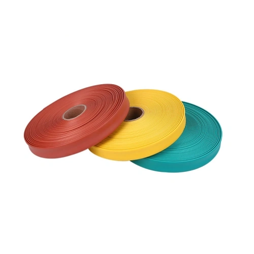
The product is shown in red, yellow and green continuous rolls. These are catalog color options, and the buyer should state the required colors when ordering.
Color selection should follow the relevant project’s busbar identification requirements. Neither the photograph nor the color alone identifies a 10kV or 35kV product, and the same color should not be used as evidence that two tubes have identical electrical properties.
For an order involving multiple phases, confirm the required colors, quantities and installed identification method against the applicable equipment specification.
Insulation Coverage Has Limits
The catalog describes busbar heat shrink tubing as protection against accidental contact, foreign objects and conditions associated with contamination or moisture. Such coverings can reduce exposure of conductive surfaces, but they are not a substitute for a properly designed insulating system.
RIKI publishes a material breakdown strength of at least 25 kV/mm. That is a material test value. It is not proof that any length of covered busbar will withstand a particular system test voltage once installed inside a switchgear cabinet.
Required phase-to-phase and phase-to-earth clearances must be established from the equipment design, applicable standards and qualification evidence. The use of insulation sleeves should not be taken as permission to reduce those distances by an assumed amount.
Bolted connections, terminals and irregular junctions may also need a different insulating component or an approved supplementary treatment. A straight continuous tube cannot be assumed to fit every connection shape.
Order by the Finished Busbar Design
For a new switchgear project, the most useful document is a busbar layout drawing showing widths, thicknesses, bends, joint locations and required covered lengths. A flat bar and a formed busbar with the same nominal width may not have the same tubing installation requirements.
Specify the voltage family, MPG ordering code, color and required roll or cut length. Check whether the tubing must pass over joints or hardware before shrinking, and obtain dimensional approval if the geometry differs from a straight bar.
The catalog publishes the continuous tubing range but does not establish a standard roll length for every SKU. Packaging lengths and any project-specific tests should therefore be confirmed with the quotation rather than inferred from the product image.