24kV Three-Core Heat Shrink Straight-Through Joint
- 24kV three-core heat shrink straight-through joint kit for 12/20kV XLPE-insulated power cables.
- Available in four conductor cross-section ranges: 25–50, 70–120, 150–240 and 300–500 mm².
- Designed for joining two three-core cable lengths through individual conductor connections and a common joint protection arrangement.
- Joint planning must account for cable preparation lengths, conductor connector positions, screen and armour restoration, and the working space needed for heat shrink installation.
Before Splicing Three Cores: Check the Available Jointing Space
The cable schedule says 12/20kV, three cores and 240 mm². Both cable ends are already at the jointing location. Is there enough prepared cable length and working space to complete the three connections, install the heat shrink components and close the joint assembly correctly?
That question should be addressed before installation begins, not after the cable sheaths have been removed.
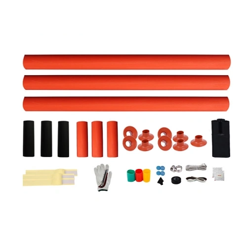
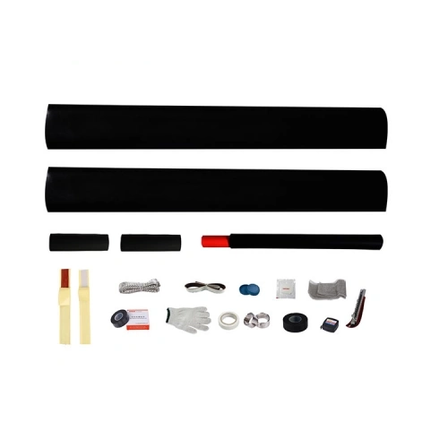
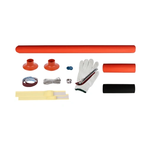
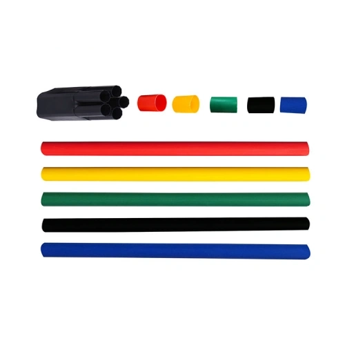
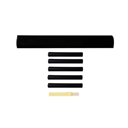
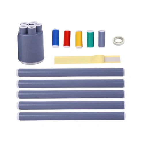
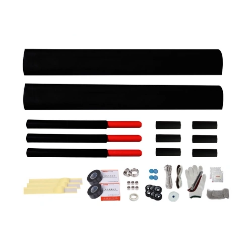
RIKI’s 24kV three-core heat shrink straight-through joint range is intended for XLPE-insulated power cables. Four conductor-size selections cover 25–50, 70–120, 150–240 and 300–500 mm². The illustrated kit contains two long black tubes, three smaller red-ended sleeve assemblies and other accessories associated with the jointing process.
The Space Occupied by Three Connections
Each conductor in a three-core cable must be connected to its corresponding conductor on the opposite cable end. The prepared cores, connectors and surrounding insulation components all occupy space within the finished joint.
The jointing instructions determine the required conductor preparation lengths and relative connection positions. Depending on the approved kit design, connections may need particular axial positioning or separation to accommodate the insulation and protection components. An installer should not choose aligned or staggered connection positions simply from the product photograph.
The completed joint may occupy considerably more space than the original cable diameter. Where the installation is inside a restricted chamber, cable route or enclosure, the available longitudinal space and permitted cable bending must be checked against the actual joint assembly dimensions.
Two Cable Ends Mean Two Sets of Measurements
On a new installation, both cable lengths may have been supplied to the same specification. During a repair, however, the original cable and its replacement may differ in insulation diameter, metallic screening or outer sheath construction.
The catalog conductor range does not establish that two cables with different constructions can automatically be joined using the same standard kit. A compatibility review should use the specifications of both cable ends, including:
- Conductor material and nominal cross-section.
- Outside diameter over the prepared XLPE insulation.
- Metallic screen type, construction and bonding requirements.
- Armour type and outer sheath dimensions, where applicable.
- Connector dimensions and the intended connection method.
This is particularly important when the joint replaces a damaged section of an existing feeder. The new cable may carry the same nominal voltage and conductor area without having identical dimensions.
Heating Access Is an Installation Constraint
The heat shrink components must be positioned and recovered according to the supplied installation procedure. Adequate access is needed to apply heat around the required circumference and length without damaging adjacent cable materials or components.
Restricted access should be identified during work planning. The type of heating equipment, allowable cable preparation dimensions and component recovery sequence are determined by the installation instructions, not by a universal heating temperature or time.
After the individual conductor connections have received their required electrical insulation and screening treatment, the completed assembly must also have the specified outer protection. The exact function and sequence of the illustrated sleeves should be confirmed from the product-specific instructions.
The Material Schedule Should Include More Than the Joint Kit
A three-core joint may require conductor connectors, metallic screen restoration accessories, earthing or bonding components and provisions for the outer cable construction. The actual supply package must be agreed for the specified cable, particularly if armoured cable is involved.
The photo identifies the jointing product family but does not prove that every connector or earthing accessory is included in each size selection.
For project procurement: provide the cable datasheets for both ends, the proposed joint location, available working dimensions and installation environment. This allows the selected kit and accessory configuration to be reviewed before the cable is cut or the purchase order finalized.
24kV Three-Core Joint Size Selection and Technical Specifications
| Product Name | 24kV Three-Core Heat Shrink Straight-Through Joint |
|---|---|
| Brand | RIKI |
| Manufacturer | Zhejiang Ruikai Electric |
| Product Category | Heat Shrink Cable Accessories |
| Product Type | Medium Voltage Straight-Through Joint |
| Catalog Voltage Class | 20kV (24kV) |
| Applicable Cable Voltage Designation | 12/20kV |
| Cable Configuration | Three-Core |
| Applicable Cable Insulation | XLPE |
| Joint Configuration | Straight-Through / In-Line |
| Installation Technology | Heat Shrink |
| Heating Requirement | External heating required for heat shrink recovery |
| Conductor Connections | Three individual conductor connections per three-core joint |
| Visible Kit Components | Two large black tubes, three smaller red-ended sleeve assemblies and other illustrated accessories |
| Available Conductor Cross-Sections | 25–500 mm² across four selections |
| SKU and Applicable Cable Section | |
| SKU: JSY-24/3.1 | 25–50 mm² |
| SKU: JSY-24/3.2 | 70–120 mm² |
| SKU: JSY-24/3.3 | 150–240 mm² |
| SKU: JSY-24/3.4 | 300–500 mm² |
The published conductor ranges and product classification follow RIKI’s 20kV (24kV) heat shrink cable accessory catalog. The actual cable construction, connector dimensions, jointing space and restoration requirements must be verified before final selection. The table does not establish individual SKU certification, direct-burial suitability or the complete bill of materials.
Frequently Asked Questions (FAQ)
How much working space is needed for a three-core heat shrink joint?
There is no universal working-space dimension that can be determined from the conductor cross-section alone. The installer needs sufficient room for cable preparation, connector installation, component positioning and controlled heating. Check the required joint length and finished dimensions against the available space, cable bending limits and the instructions supplied for the selected kit.
Must the three conductor connections be staggered along the cable?
Follow the connection positions and preparation dimensions specified for the selected joint kit. Some jointing arrangements require particular axial positions to accommodate the connector and insulation components, but this cannot be decided from the photograph alone. Do not assume that aligned or staggered connections are acceptable without checking the applicable installation instructions.
Can heat shrink jointing be performed in a confined cable chamber?
Only where the site conditions permit the approved installation method and safe use of the required heating equipment. Restricted access may prevent even heating or proper component positioning. Before starting, review working clearances, ventilation, combustible materials and applicable site safety procedures. The use of a heat shrink kit does not override confined-space or hot-work requirements.
What should be checked before the outer joint covering is completed?
Verify the conductor connections, cable preparation dimensions and positioning of the required insulation and screening components against the approved instructions. Confirm that the metallic screen and any armour restoration have been addressed for the actual cable design. Any required inspection records or tests should follow the project procedure before the assembly is closed.
Cable Repair and Feeder Jointing Where Three-Core Connections Are Required
Planned Feeder Extensions
Connecting two compatible lengths of three-core XLPE power cable at a designated jointing location along a medium-voltage feeder.
12/20kV · Three-Core Cable
Faulted Cable Section Replacement
Rejoining a feeder after a damaged section is removed, provided the retained and replacement cables are suitable for the selected joint.
Cable Repair · Joint Reconstruction
Industrial MV Cable Routes
Three-core cable jointing in industrial distribution projects where cable construction and the available installation space have been verified.
Industrial Distribution · XLPE
Pre-Planned Jointing Locations
Projects where cable access, preparation lengths and heating clearances are reviewed before scheduling the jointing work.
Site Planning · Cable Installation