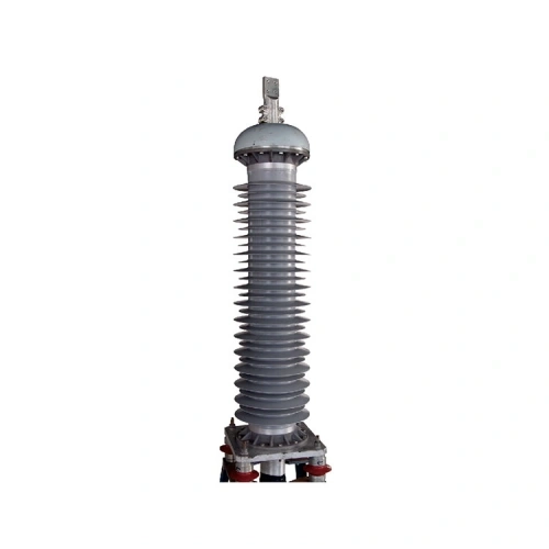
64/110kV Outdoor Cable Termination with Composite Insulator
The RIKI 64/110kV outdoor cable termination uses a composite insulator with silicone rubber sheds and is designed for single-core XLPE power cables. Its construction includes a glass-fiber-reinforced epoxy tube and a prefabricated stress cone, with eight catalog conductor-size options from 240 to 1200 mm². Cable dimensions, mounting-flange requirements and project qualification documents should be checked before the termination is specified for an outdoor high-voltage installation.
A Composite Insulator Changes the Outdoor Terminal Assembly, Not the Cable Rating
For a 110kV outdoor cable termination, the insulator is not merely a protective cover. It forms part of a complete high-voltage assembly, with defined interfaces at the conductor connection, cable insulation system and supporting structure.
The RIKI composite-insulator termination is listed for 64/110kV XLPE cables. Its external insulation combines a glass-fiber-reinforced epoxy tube with silicone rubber sheds. Aluminum-alloy flanges are used at the ends of the composite assembly, according to the manufacturer’s product description.
Composite Outside, Liquid-Filled Inside
The model designation identifies a composite-sleeve outdoor termination with liquid internal insulation. It should not be confused with a fully dry-type outdoor termination simply because the external insulator uses polymeric materials.
The illustrated structure includes a prefabricated stress cone inside the termination. This component forms part of the insulation and electric-field control arrangement at the prepared cable end. Its dimensions and positioning must correspond to the specified XLPE cable and installation instructions.
Silicone rubber sheds form the ribbed external surface visible in the photograph. Their geometry is relevant to outdoor insulation performance, especially where contamination and surface moisture are considerations. The actual creepage distance and pollution qualification must be verified from the applicable composite-terminal documentation.
The Mounting Flange Is Part of the Specification
The cable conductor size may be stated clearly in a purchasing request while the support structure is left undefined. That is a problem for a large outdoor termination. The mounting arrangement must match the site’s mechanical interface, cable entry direction and available support.
RIKI’s catalog provides a flange drawing for this product family, together with a structural diagram identifying the mounting flange, terminal lug, sealing components, stress cone and cable tail arrangement.
Before the termination is approved for a project, the buyer should compare the current product drawing with the equipment support and cable installation drawings. The dimensions of the mounting interface, terminal connection and cable entry should be confirmed before fabrication or installation work proceeds.
Eight Conductor Sizes, One Product Family
The manufacturer’s model table lists eight single-core XLPE conductor options: 240, 300, 400, 500, 630, 800, 1000 and 1200 mm².
These are published nominal conductor sizes, not a universal insulation-diameter range. Cables of the same conductor area may differ in insulation construction or metallic-screen arrangement. The cable datasheet and the product-specific dimensional requirements should therefore be reviewed together.
There is also a distinction between the catalog’s general product family and the final delivery configuration. Terminal lug dimensions, mounting components, filling arrangements and other accessories should be established through the approved technical drawing and bill of materials.
Documentation Before High-Voltage Project Approval
The RIKI catalog refers to IEC 60840 and GB/T 11017.3 for its 110kV cable accessory series. A reference to these standards is useful when reviewing the product family, but the applicable test report and product scope must be confirmed for the proposed termination.
The procurement review should identify the required type-test documentation, cable compatibility details, installation instructions and technical drawings. Site conditions such as installation altitude, environmental exposure and mechanical loading may also affect the final specification.
For a tender or utility project, request the documentation against the selected composite-insulator model rather than using a report associated only with a porcelain-insulator or dry-type variant.
64/110kV Composite Termination — Construction and Cable Size Options
| Product Name | 64/110kV Outdoor Cable Termination with Composite Insulator |
|---|---|
| Model | YJZWY4-64/110kV |
| Brand | RIKI |
| Manufacturer | Zhejiang Ruikai Electric |
| Product Category | High Voltage Cable Accessories |
| Product Type | Outdoor High Voltage Cable Termination |
| Rated Voltage (U0/U) | 64/110kV |
| Applicable Cable Type | Single-Core XLPE-Insulated Power Cable |
| External Insulator | Composite Insulator |
| Composite Insulator Construction | Glass-Fiber-Reinforced Epoxy Tube with Silicone Rubber Sheds |
| Flange Material | Aluminum Alloy (as described in the catalog) |
| Internal Insulation Arrangement | Liquid-Filled |
| Electrical Stress Control | Prefabricated Stress Cone |
| Installation Environment | Outdoor |
| Published Conductor Size Options | 240–1200 mm², eight listed sizes |
| Catalog Conductor Size Selections | |
| Size Option 1 | 1 × 240 mm² |
| Size Option 2 | 1 × 300 mm² |
| Size Option 3 | 1 × 400 mm² |
| Size Option 4 | 1 × 500 mm² |
| Size Option 5 | 1 × 630 mm² |
| Size Option 6 | 1 × 800 mm² |
| Size Option 7 | 1 × 1000 mm² |
| Size Option 8 | 1 × 1200 mm² |
The model and eight conductor sizes follow the published RIKI type table. This table does not establish an approved insulation-diameter range, individual test certification, or compatibility with every 110kV cable construction. Final selection requires the applicable composite-termination drawings, cable data and project qualification documents.
Frequently Asked Questions (FAQ)
Is this a porcelain-insulator or composite-insulator termination?
This product is the composite-insulator version. The catalog describes an external insulating structure made from a glass-fiber-reinforced epoxy tube and silicone rubber sheds. Although porcelain-insulator terminations belong to the same general high-voltage cable accessory category, their structures and technical specifications should not be treated as interchangeable.
Does a composite insulator mean the termination is completely dry-type?
No. The composite description refers to the external insulating structure. The RIKI catalog model explanation identifies this termination as a liquid-filled design. It should therefore be distinguished from a separately specified dry-type outdoor termination. The internal filling arrangement and installation requirements should be confirmed through the product-specific technical documentation.
What conductor sizes are listed for this 64/110kV composite termination?
The published type table lists eight single-core conductor sizes: 240, 300, 400, 500, 630, 800, 1000 and 1200 mm². These are nominal conductor cross-sections. The required cable insulation diameter, conductor connection and other dimensional limits must be verified separately for the selected configuration.
What should be checked before approving the mounting arrangement?
Review the current mounting-flange drawing, supporting structure, cable entry direction and terminal connection dimensions. The published catalog includes a flange illustration, but project approval should use the applicable detailed drawing. The required mechanical loading and installation orientation must also agree with the approved product configuration.
Does the IEC 60840 reference prove certification for every supplied configuration?
No. The catalog references IEC 60840 for its 110kV cable accessory series, but a general standards reference should not be presented as an individual product certificate. Where a project requires type-test or qualification evidence, request the relevant documents and verify that their scope covers the proposed composite-insulator termination and cable configuration.
High-Voltage Cable-to-Equipment Transitions in Outdoor Installations
Outdoor Substation Cable Ends
Terminating compatible high-voltage XLPE cables at outdoor substation connection points where the insulator and supporting structure form part of the approved equipment arrangement.
Key check: Terminal interface and support design
Underground-to-Overhead Transitions
Projects where an XLPE cable route emerges at an outdoor connection location and requires a separately supported high-voltage termination before connection to overhead equipment.
Key check: Cable riser geometry and mechanical support
High-Voltage Infrastructure Upgrades
Reviewing a composite-insulator configuration for the replacement or upgrading of an existing outdoor cable termination, subject to electrical and mechanical compatibility.
Key check: Existing flange and cable dimensions
Utility and EPC Material Approval
Preparing technical submissions for high-voltage cable projects where model identification, cable size, structural drawings and applicable test documents must be reviewed together.
Key check: Model-specific approval documentation