64/110kV Dry-Type GIS Cable Termination
The RIKI 64/110kV dry-type GIS cable termination connects single-core XLPE power cables to compatible gas-insulated switchgear equipment. Its design combines an epoxy insulating bushing with a prefabricated stress cone held under spring pressure, without requiring insulating oil or gas filling inside the cable termination. Two insertion-height configurations are indicated in the catalog, so GIS interface drawings and cable dimensions must be reviewed before ordering.
The GIS Interface Comes First — Before the XLPE Cable Is Prepared
A GIS cable bay and a high-voltage cable termination may both be specified for 110kV service and still fail to fit together. The problem is not necessarily electrical rating. The insertion depth, contact position and equipment-side interface may be different.
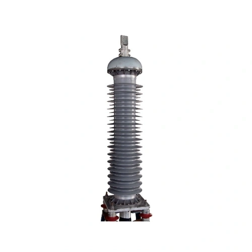
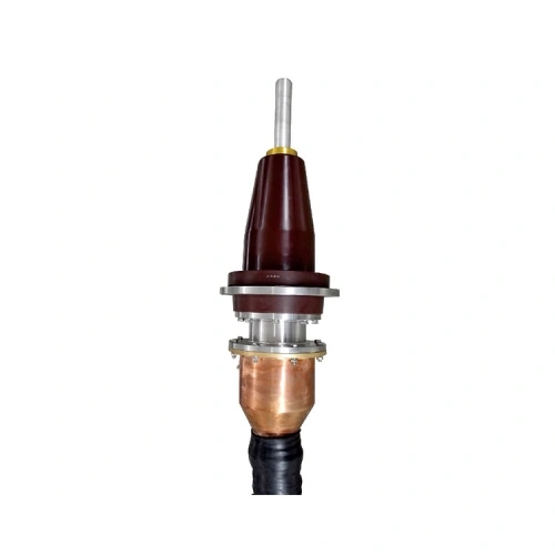
RIKI’s 64/110kV dry GIS termination is intended for XLPE-insulated cables connected to suitable gas-insulated electrical equipment. The catalog shows a compact assembly with a contact terminal, epoxy bushing, prefabricated stress cone and metallic lower housing. The cable enters from below, while the upper contact and insulating interface connect toward the equipment.
470 mm or 757 mm Is a Design Decision
The technical table gives two insertion heights: 470 mm and 757 mm. These should not be treated as interchangeable dimensions or selected according to installation preference.
The correct interface depends on the receiving GIS equipment and the approved cable connection arrangement. Before a termination is ordered, the switchgear manufacturer’s interface drawing should establish the required insertion height, contact geometry, flange details and associated dimensional tolerances.
RIKI’s older catalog refers to IEC 60859 for GIS mounting interfaces. That publication has been superseded by the IEC 62271-209 series. Project requirements should therefore be checked against the applicable current interface standard and the equipment manufacturer’s approved drawings. A catalog reference alone does not demonstrate compliance with the latest edition.
Spring Pressure at the Stress Cone Interface
Inside the termination, the prefabricated stress cone works with an epoxy insulating bushing. The catalog describes a spring assembly that maintains contact pressure between the stress cone and the inner surface of the epoxy component.
This contact is relevant to the electrical insulation interface. The assembly must provide the intended fit without relying on an installer to improvise the pressure or component position. Spring dimensions, cable insulation diameter and installation tolerances need to correspond to the specified termination configuration.
The product’s dry-type construction also matters here. The catalog identifies a silicone rubber-based dry insulation arrangement without the need to fill the termination itself with insulating oil or gas. That does not mean the GIS equipment has no insulating gas. The GIS enclosure and the cable termination have different insulation responsibilities, separated by the approved interface design.
Where the Supplier Responsibilities Meet
For a new GIS installation, the cable contractor and switchgear supplier may deliver different parts of the same connection. If their approved drawings do not agree, the discrepancy can surface after the equipment has arrived at site.
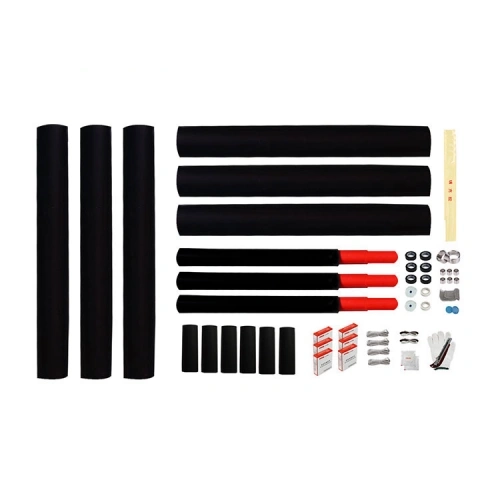
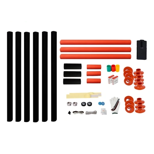
The technical submission should identify the cable termination manufacturer, the GIS equipment type, the interface drawing revision and the division of supply responsibilities. Contact terminals, connecting flanges, sealing components and any required interface hardware should be confirmed before procurement.
The assembled termination shown in the catalog includes metallic parts and an earthing terminal. Their precise connections and the relevant cable screen bonding arrangement must follow the electrical system design rather than the product photograph.
Cable Dimensions Still Define the Lower Interface
At the cable end, nominal conductor cross-section does not specify the full XLPE insulation diameter. RIKI’s type table lists eight conductor-size options from 240 to 1200 mm², while a separate technical summary mentions a wider range extending to 1600 mm².
Until that difference is clarified for the selected configuration, 1600 mm² should not be treated as a confirmed standard catalog option. For any conductor size, the actual cable insulation dimensions and screen construction must be compatible with the supplied stress-control components.
For a GIS termination RFQ, the decisive starting point is the equipment interface drawing. The cable schedule and desired termination quantity are still needed, but they cannot resolve an incompatible insertion height or contact arrangement.
64/110kV Dry GIS Termination — Interface, Construction and Cable Sizes
| Product Name | 64/110kV Dry-Type GIS Cable Termination |
|---|---|
| Model | YJZGG-64/110kV |
| Brand | RIKI |
| Manufacturer | Zhejiang Ruikai Electric |
| Product Category | High Voltage Cable Accessories |
| Product Type | Dry Insulated GIS Cable Termination |
| Rated Voltage (U0/U) | 64/110kV |
| Maximum Operating Voltage (Um) | 126kV |
| Impulse Voltage Tolerance Level | 550kV — published catalog value |
| Applicable Cable | Single-Core XLPE-Insulated Power Cable |
| Internal Insulation Arrangement | Dry Type; No Insulating Oil or Gas Filling Required Inside the Cable Termination |
| Insulating Components | Epoxy Bushing and Prefabricated Stress Cone |
| Stress Cone Interface | Spring-Loaded Contact Pressure Arrangement |
| Catalog Insertion Height | 470 mm or 757 mm — Configuration to Be Confirmed |
| Conductor Connection | Crimping — as stated in the catalog |
| Published Ambient Temperature | -40°C to +50°C |
| Approximate Weight | 60 kg — catalog reference |
| Catalog Product Standards | GB/T 11017.3 and IEC 60840 — product-family references; specific conformity documentation to be verified |
| GIS Connection Interface | Catalog references legacy IEC 60859; confirm equipment fit and requirements under applicable IEC 62271-209 edition |
| Published Conductor Size Options | |
| Option 1 | 1 × 240 mm² |
| Option 2 | 1 × 300 mm² |
| Option 3 | 1 × 400 mm² |
| Option 4 | 1 × 500 mm² |
| Option 5 | 1 × 630 mm² |
| Option 6 | 1 × 800 mm² |
| Option 7 | 1 × 1000 mm² |
| Option 8 | 1 × 1200 mm² |
The values above are drawn from the RIKI product catalog. The applicable GIS interface, insertion height, conductor size, actual cable insulation dimensions and component supply boundary must be confirmed against current technical drawings. The catalog also mentions conductor sizes up to 1600 mm² in a separate general specification, but the published ordering table ends at 1200 mm². This page does not establish 1600 mm² as a standard option or claim individual type-test certification.
Frequently Asked Questions (FAQ)
How do I choose between the 470 mm and 757 mm insertion heights?
The selection should follow the approved interface drawing for the receiving GIS equipment. Confirm the required insertion depth, contact position, flange geometry and equipment-side tolerances with the switchgear manufacturer. The catalog lists both dimensions, but it does not establish that either configuration can be fitted to every GIS bay.
Does a dry-type GIS termination require SF6 gas filling?
The RIKI dry-type cable termination does not require an insulating oil or gas filling inside the termination itself. The connected GIS equipment may still use SF6 or another insulating gas in its own enclosure. The cable termination and GIS gas compartment must be considered separately, with the required insulating barrier and interface sealing arrangement verified for the installation.
What does the spring assembly do inside the termination?
The catalog describes a compression arrangement that maintains contact pressure between the prefabricated stress cone and epoxy bushing. This is part of the designed electrical insulation interface. The spring arrangement must match the actual cable and termination configuration; its dimensions or preload should not be changed using a generic installation method.
Is a 1600 mm² cable supported by the standard GIS termination range?
The RIKI ordering table lists eight nominal conductor sizes from 240 to 1200 mm². A separate technical summary gives a broader range extending to 1600 mm². Because these entries differ, a 1600 mm² requirement needs confirmation of product availability, insulation dimensions and the applicable configuration before it can be quoted as a standard selection.
Which GIS interface standard should be specified for a new project?
The older RIKI catalog mentions IEC 60859 for GIS mounting interfaces. That publication has been replaced by IEC 62271-209. A new project should identify the applicable current edition, the receiving equipment’s approved interface drawing and any required conformity documentation. The catalog reference does not by itself certify the supplied termination against the current standard.
When the Cable-to-GIS Interface Determines the Termination Choice
New GIS Cable Bay Connections
Connecting a compatible single-core XLPE high-voltage cable to a GIS cable connection enclosure using the equipment's specified dry-type termination interface.
Primary check: Insertion height and interface geometry
GIS Equipment Replacement
Reviewing an existing cable termination arrangement when a GIS bay is replaced or modified and the new equipment may have a different cable connection interface.
Primary check: Old and new interface drawings
Transmission Cable Entry Projects
Terminating underground XLPE transmission cables at suitable GIS installations, with cable dimensions, metallic screen connections and equipment-side sealing arrangements confirmed.
Primary check: Cable preparation and GIS boundary
EPC Interface Coordination
Preparing a joint technical submission between the switchgear supplier, cable accessory supplier and installation contractor before ordering and site assembly.
Primary check: Drawing revision, supply limits and approvals