Joining Matching Cable Lengths
In-line connections between two compatible three-core XLPE cable sections in a planned medium-voltage feeder installation.
Main check: Identical or approved cable construction

The RIKI 35kV three-core heat shrink straight-through joint is offered for 21/35kV and 26/35kV XLPE-insulated power cable families, with conductor-size selections of 50–120, 150–240 and 300–500 mm². The published catalog identifies three dedicated three-core joint ordering codes, distinct from the single-core splice and cable termination ranges. Project buyers should check both cable ends, the specified joint components and the required acceptance documents before confirming supply.
Receiving a 35kV three-core heat shrink joint kit is not quite the same as receiving a single insulating component. The package must support three conductor connections and the restoration of the corresponding cable insulation and protective systems. Missing or incorrectly specified components may only become apparent after the jointing work has started.
RIKI lists its three-core heat shrink straight joint under the 35kV cable accessory range for 21/35kV and 26/35kV XLPE-insulated power cables. Unlike the lower-voltage heat shrink joint ranges, this family has three published conductor-size selections: 50–120, 150–240 and 300–500 mm².
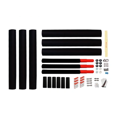
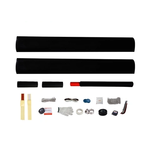
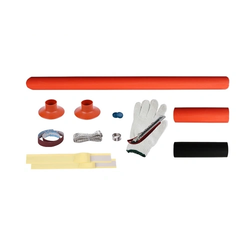
The product image displays three long black tubes on one side, three additional long black tubes, three shorter assemblies with red ends, and a collection of smaller sleeves and jointing accessories.
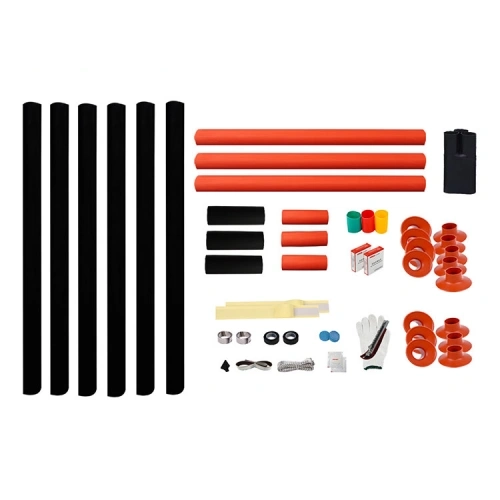
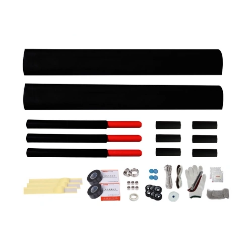
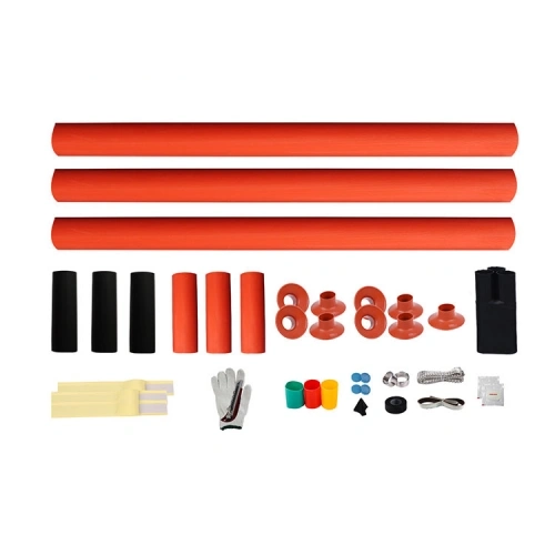
This visual arrangement is useful for identifying the three-core product family, but it is not a substitute for a component drawing or packing list. The precise role of every tube, the required quantity of each component and the installation sequence must be established from the supplied technical instructions.
In particular, the image should not be used to assume that every conductor connector, screen bonding component or armour-restoration accessory is included as standard.
The 35kV catalog family includes two XLPE cable voltage designations. The actual insulation construction may differ between cables specified as 21/35kV and 26/35kV, even where the conductor cross-section is the same.
These distinctions are important for a straight-through joint because both cable ends must match the joint’s approved dimensional and electrical requirements. Insulation outside diameter, conductive screen preparation and connector dimensions should be checked independently of the nominal conductor-size bracket.
The catalog does not establish that a joint can directly connect a 21/35kV cable to a 26/35kV cable. Such a transition would require a specific engineering and product-compatibility review rather than selection by the common 35kV label.
A complete joint enquiry should identify the two cable ends being connected. Where both cables share the same construction, one cable specification may be sufficient for preliminary review. Where they differ, the original and replacement cable datasheets should be supplied separately.
Useful information includes the cable voltage designation, conductor material and cross-section, XLPE insulation outside diameter, metallic-screen construction and any armour or sheath details affecting the joint assembly.
The corresponding connector arrangement should also be defined. A conductor connector must be suitable for its electrical application while physically accommodating the surrounding insulation and jointing components.
Before releasing material for installation, the project team should compare the selected product code, package contents and technical documents with the approved material schedule. The intended splice configuration should be traceable to the supplied installation instructions and any project-specific acceptance documents.
RIKI publishes electrical test references for its 35kV heat shrink accessory series. Those figures help identify the catalog’s technical scope but should not be treated as separate third-party certificates for each straight-joint ordering code.
The final protective arrangement must also be appropriate for the installation environment. A heat shrink joint cannot be assumed suitable for direct burial, permanent immersion or a specific ingress-protection classification simply because it is intended for medium-voltage power cable splicing.
For procurement: approve the product as a complete three-core jointing configuration, not simply as a 35kV tube set. The cable pair, conductor-size selection, accessory list and required documentation should agree before bulk ordering.

| Product Name | 35kV Three-Core Heat Shrink Straight-Through Joint |
|---|---|
| Brand | RIKI |
| Manufacturer | Zhejiang Ruikai Electric |
| Product Category | Heat Shrink Cable Accessories |
| Product Type | Medium Voltage Straight-Through Cable Joint |
| Catalog Voltage Class | 35kV |
| Catalog Cable Voltage Designations | 21/35kV and 26/35kV |
| Cable Configuration | Three-Core |
| Applicable Cable Insulation | XLPE |
| Joint Configuration | Straight-Through / In-Line |
| Installation Technology | Heat Shrink |
| Heating Requirement | External heating required for heat shrink recovery |
| Illustrated Kit Components | Long black tubes, three red-ended sleeve assemblies, shorter insulating components and assorted jointing accessories |
| Number of Conductor Connections | Three per three-core straight-through joint |
| Available Conductor Cross-Sections | 50–500 mm² across three selections |
| SKU and Applicable Conductor Cross-Section | |
| SKU: JSY-35/3.1 | 50–120 mm² |
| SKU: JSY-35/3.2 | 150–240 mm² |
| SKU: JSY-35/3.3 | 300–500 mm² |
The voltage designations and conductor-size selections follow RIKI’s published 35kV heat shrink accessory catalog. Confirm the cable construction on both sides of the joint, connector dimensions and the accessory configuration before ordering. Environmental suitability, product-specific tests and certification documents must be verified separately.
Do not assume direct compatibility. Although both voltage designations appear in RIKI’s 35kV accessory range, the two cables may have different insulation thicknesses, insulation outside diameters or screen constructions. Connecting them requires a review of both cable specifications and the approved joint design. The common 35kV classification alone does not authorize a transition between different cable voltage constructions.
The image helps identify the three-core joint family and shows multiple tubing assemblies, but it is not a confirmed packing list. The exact functions and supplied quantities of conductor connectors, insulating sleeves, screen bonding materials and other accessories should be checked against the bill of materials for the selected ordering code. Request that information before approving a large project order.
Not as a direct substitution. A three-core cable includes a common sheath and may have shared armour or other protective elements that must be addressed where the three cores are prepared for joining. Separate single-core joint kits do not automatically include the components needed to restore the complete three-core cable assembly. Any alternative configuration requires a specific engineering review.
No. Outer tubing appearance does not establish the completed assembly’s sealing, mechanical protection or long-term environmental suitability. Direct-burial applications require confirmation of the complete joint system against the project’s installation conditions and relevant test documentation. The published conductor-size table alone does not provide a direct-burial qualification.
In-line connections between two compatible three-core XLPE cable sections in a planned medium-voltage feeder installation.
Main check: Identical or approved cable construction
Replacing a damaged section of a three-core feeder where the retained and new cables may have different dimensions or screening arrangements.
Main check: Specifications for both cable ends
Organizing multiple jointing kits by conductor-size selection, planned joint location and required accessory configuration.
Main check: SKU and approved bill of materials
Replacing an existing medium-voltage joint where cable condition, installation environment and acceptance documentation must be reviewed before work begins.
Main check: Cable suitability and project approval